

Machine Vision Coordinate Systems and Camera Intrinsic Matrix Guide
- por TofSensor
How Do Coordinate Systems and Camera Intrinsic Parameters Work in Machine Vision?
In computer vision (computer vision definition), understanding different coordinate systems—such as camera coordinates, image coordinates, and world coordinates—is fundamental for building vision systems and achieving tasks like 3D reconstruction, pose estimation, localization, navigation, and object tracking. Meanwhile, camera intrinsic parameters (camera matrix intrinsic) and extrinsic parameters determine how image projections map to real-world space. This article provides an in-depth explanation of the image space coordinate system, camera matrix intrinsic, world coordinate system (world matrix), and camera parameters in machine vision, helping developers gain a deeper understanding of visual geometry principles.
What is the Image Space Coordinate System
The image space coordinate system is the core reference framework for describing pixel positions in a 2D image and is one of the most fundamental geometric concepts in computer vision. In a digital image, each pixel has a corresponding 2D coordinate, usually denoted as (u, v):
-
u: The horizontal pixel position, typically with the image’s top-left corner as the origin
-
v: The vertical pixel position, usually counted from top to bottom
Pixel coordinates are typically integers representing row and column indices. However, these coordinates only describe positions in the 2D image plane and do not include real-world depth or 3D information. Therefore, the image space coordinate system provides a 2D visual description and forms the first layer of geometric information in vision perception.
Functions of the Image Space Coordinate System
-
Feature Extraction:
Pixel coordinates provide precise indexing for feature points (e.g., corners, edges, SIFT/SURF features), forming the basis for matching and recognition. -
Object Detection and Recognition:
Pixel coordinates locate bounding boxes or key points of objects in images, enabling accurate positioning of objects or faces. -
Image Registration and Alignment:
In multi-view or multi-frame processing, pixel coordinates are used for alignment, transformation, and stitching to maintain spatial consistency across the vision system. -
Bridge to 3D Space:
While pixel coordinates themselves do not contain depth information, they are a critical intermediate step for linking camera coordinates and world coordinates. Using the camera intrinsic matrix (camera matrix intrinsic) and projection models, 2D pixel coordinates can be mapped to 3D space, enabling 3D reconstruction, pose estimation, and depth sensing. -
Applications in Machine Vision and AI:
In autonomous driving, robot navigation, industrial inspection, and AR/VR interaction, the image space coordinate system is the first step in processing image data, calculating features, and generating visual perception models. All advanced vision tasks rely on it as a foundation.
Extended Understanding
-
The image space coordinate system usually assumes the origin at the top-left corner, with the X-axis pointing right and the Y-axis pointing down.
-
For high-precision applications (e.g., sub-pixel feature extraction), floating-point coordinates can be used for more refined analysis.
-
In multi-camera or stereo vision systems, image space coordinates are fundamental for matching features across images, computing disparities, and generating 3D point clouds.
In summary, the image space coordinate system is not just a tool for describing 2D pixel locations—it is the first step in implementing computer vision, depth perception, and 3D reconstruction, and it underpins all vision algorithms and applications.

World Coordinate System and Object Localization
The world coordinate system (world matrix / world coordinate system) is a global reference system used to describe the real-world positions of objects in 3D space. It typically consists of three axes: X, Y, Z, which provide a unified framework to describe the locations of all objects in the scene.
Compared to image coordinates, the world coordinate system has the following characteristics:
-
Describes real 3D spatial positions
-
Supports camera pose estimation and 3D reconstruction
-
Enables spatial alignment across multiple cameras
-
Often tied to application-specific coordinate systems (e.g., robot world coordinates, map coordinates, calibration board coordinates)
The world coordinate system is essential for 3D localization, depth estimation, and SLAM algorithms.
Camera Coordinate System and Projection
The camera coordinate system is a 3D coordinate system with the camera at its origin, used to describe object positions relative to the camera. Typically, the camera coordinate axes are defined as:
-
Xc, Yc, Zc: Camera axes
-
Origin at the camera optical center
-
Zc axis generally points along the camera optical axis (forward direction)
A 3D point in the world coordinate system is usually denoted as (Xw, Yw, Zw). Using the camera’s extrinsic parameters (rotation matrix and translation vector), it can be transformed into camera coordinates (Xc, Yc, Zc). This step is crucial for multi-view geometry and 3D reconstruction.
Transforming from Camera Coordinates to Image Coordinates
Mapping from camera coordinates to image space coordinates typically involves two steps:
-
Perspective Projection:
A 3D point in the camera coordinate system (Xc, Yc, Zc) is projected onto the normalized image plane as (x, y):
-
Pixel Coordinate Transformation:
The normalized coordinates are scaled and offset by the camera intrinsic matrix (camera matrix intrinsic) to obtain image pixel coordinates (u, v):
Where K is the camera intrinsic matrix:
K=fx000fy0cxcy1-
f_x, f_y: Focal lengths in pixel units
-
c_x, c_y: Optical center coordinates in pixels
Through this process, real-world 3D points are mapped accurately onto the image pixel plane, forming the basis for 3D reconstruction, pose estimation, and depth perception.
Detailed Explanation of Camera Intrinsic and Extrinsic Parameters in Machine Vision
Camera intrinsic parameters describe the geometric characteristics of the camera imaging system. The main components include:
-
Focal length: Determines the field of view and projection scale
-
Principal point: The center of the image plane
-
Pixel scale factors: Usually denoted as f_x and f_y
Through camera calibration, the intrinsic matrix K (camera matrix intrinsic) can be obtained. This matrix forms the core foundation for 3D reconstruction, depth estimation, and image rectification.
Camera Extrinsic Parameters
Camera extrinsic parameters consist of a rotation matrix and translation vector, describing the spatial relationship between the world coordinate system and the camera coordinate system:
XcYcZc=RXwYwZw+tWhere:
-
R: 3×3 rotation matrix
-
t: 3×1 translation vector
Extrinsic parameters are commonly used in multi-view registration, visual localization, and 3D model fusion.
Geometric Relationships Between Coordinate Systems
In computer vision (computer vision definition), understanding the mapping between different coordinate systems is critical. A 3D point undergoes several coordinate transformations before being mapped to a pixel coordinate:
World Coordinates → Camera Coordinates → Normalized Plane Coordinates → Pixel Coordinates
Each step relies on intrinsic and extrinsic parameters. Mastering coordinate transformations is essential for 3D reconstruction, pose estimation, SLAM, and stereo vision.
Camera Calibration and Parameter Acquisition
To obtain accurate camera matrix intrinsic and extrinsic matrices, camera calibration algorithms are employed. Common calibration methods include:
-
Checkerboard calibration boards
-
Stereo calibration
-
Camera scanning datasets
By capturing multiple images from different angles, intrinsic and extrinsic parameters are estimated using least squares optimization, minimizing the reprojection error.

Typical Applications in Machine Vision
A deep understanding of image space coordinate system, camera matrix intrinsic, and world matrix is fundamental for modern machine vision systems. These coordinate systems and camera parameters not only determine the mapping from image to 3D space but also directly affect algorithm accuracy and system performance. Here are some key applications:
1. 3D Reconstruction and Point Cloud Generation
By combining image space coordinates from multiple viewpoints with intrinsic and extrinsic matrices, the 3D structure of a scene can be accurately reconstructed. Applications include:
-
3D point cloud generation: Integrating data from multiple cameras or depth sensors to create complete 3D point clouds for industrial inspection or environment modeling
-
High-precision 3D model reconstruction: Producing manipulable virtual models for architectural design, cultural heritage digitization, or virtual reality scene construction
-
Multi-view geometry processing: Using world coordinates to unify image coordinates from multiple views for accurate reconstruction and texture mapping
3D reconstruction is a core technology for robot navigation, autonomous driving, and AR/VR immersive applications.
2. Pose Estimation and Object Localization
Using mappings between image coordinates, camera intrinsics, and world matrix, the position and orientation (pose) of objects or robots in real-world space can be estimated. Applications include:
-
Robot motion control: Precisely grasping or avoiding obstacles by detecting object positions and orientations
-
Drone localization and flight control: Determining a drone’s spatial position from visual data for stable flight and autonomous navigation
-
AR object tracking: Accurately overlaying virtual objects in AR scenarios, maintaining spatial consistency with the real world
Pose estimation is crucial for vision-guided autonomous systems, intelligent manufacturing, and spatial interaction.
3. Multi-Camera System Alignment
In large-scale machine vision systems, multiple cameras often cooperate to capture scene information. The world coordinate system provides a unified reference, enabling:
-
Multi-view fusion: Combining data from different cameras to construct a global 3D scene
-
Spatial consistency processing: Aligning object coordinates across different camera views to avoid misalignment
-
Multi-view monitoring and inspection: Full coverage monitoring in industrial assembly lines, smart warehouses, and security systems
Multi-camera alignment is essential for high-precision industrial measurement, automated production, and 3D scanning systems.
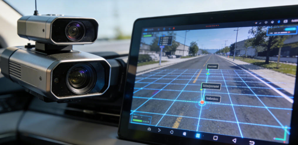
4. Depth Camera and LiDAR Fusion
In modern depth sensing systems, a single sensor often cannot meet the perception requirements of complex environments. By combining camera parameters, image coordinates, and world coordinate mapping, depth cameras and LiDAR data can be fused to achieve more accurate spatial understanding:
-
Multi-source data integration: Combining high-precision depth from LiDAR with camera RGB or depth data
-
3D scene reconstruction: Fusing point clouds and vision information to create high-resolution 3D environment models
-
Intelligent decision support: Providing reliable spatial perception data for autonomous driving, robot path planning, and smart security
-
Environmental understanding and dynamic adaptation: Enhancing robustness under varying light conditions, complex backgrounds, and dynamic scenes
Depth camera and LiDAR fusion is a core method for high-precision spatial perception, autonomous driving, intelligent robotics, and industrial inspection.
By thoroughly understanding image space coordinate system, camera matrix intrinsic, and world matrix, developers can build high-precision, robust, multi-sensor fused machine vision systems, providing a solid foundation for industrial automation, intelligent robotics, autonomous vehicles, and AR/VR applications.
Summary
In machine vision and computer vision (computer vision definition) systems, mastering concepts such as image space coordinate system, camera matrix intrinsic, and world matrix is critical for understanding visual geometry, performing 3D reconstruction, localization, and multi-view fusion. By leveraging coordinate mappings and parameter estimation, developers can build more robust, accurate, and reliable visual perception systems.
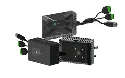
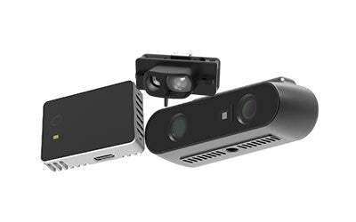
3D Safe Guarding Privacy RGBD Camera Synexens CS30

After-sales Support:
Our professional technical team specializing in 3D camera ranging is ready to assist you at any time. Whether you encounter any issues with your TOF camera after purchase or need clarification on TOF technology, feel free to contact us anytime. We are committed to providing high-quality technical after-sales service and user experience, ensuring your peace of mind in both shopping and using our products.