

Machine Vision Coordinate Systems & OpenCV Camera Parameters Explained
- Posted by TofSensor
What are machine vision coordinate systems and how does OpenCV handle camera parameters in industrial vision?
In industrial automation and machine vision inspection, the machine vision system coordinate system and camera parameters are the fundamental basis for high-precision measurement, 3D reconstruction, and robot positioning. Especially when using the OpenCV coordinate system for image processing and 3D vision development, understanding the transformation relationships between different coordinate systems is essential, such as pixel coordinates, image coordinates, camera coordinates, and world coordinates.
This article systematically explains key concepts in industrial vision systems, including camera intrinsics, extrinsics, and coordinate transformation methods, combined with trending keywords such as 3D vision, ToF camera, point cloud generation, and camera calibration.
What is machine vision in industrial automation?
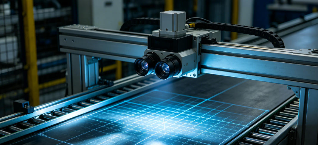
Machine vision in industrial automation refers to the technology that enables machines to 'see' and interpret production environments using cameras, image processing algorithms, and AI. It is widely used in automated inspection, dimensional measurement, defect detection, and robot vision guidance, making it a core technology for smart factories.

1. Four Core Coordinate Systems in Machine Vision
In industrial vision systems, the machine vision coordinate system is the foundation for understanding imaging principles, 3D reconstruction, and measurement tasks. Whether in industrial inspection, robot grasping, SLAM navigation systems, or 3D vision measurement, a clear coordinate definition and transformation chain is essential.
A complete vision system typically includes four coordinate systems, forming a full mapping pipeline from real-world space to image data.
1. World Coordinate System
The world coordinate system describes object positions in real 3D space and serves as the global reference frame of the vision system. In industrial environments, it is often aligned with factory reference points, production lines, or robot workstations.
In applications such as robot vision guidance, AGV path planning, and automated assembly systems, the world coordinate system defines absolute object positions. Through calibration, data from multiple cameras or devices can be unified into a single spatial coordinate framework, enabling multi-view fusion and coordinated control.
2. Camera Coordinate System
The camera coordinate system takes the camera optical center as the origin, with the Z-axis aligned along the optical axis. It serves as the intermediate bridge between 3D space and imaging.
In this system, a point is represented as (Xc, Yc, Zc), where Zc indicates depth. In depth cameras and ToF cameras, this coordinate system is critical because it directly affects depth accuracy.
In industrial 3D vision applications such as defect detection, 3D measurement, and robot picking, the camera coordinate system is essential for spatial calculations.
3. Image Coordinate System
The image coordinate system is located on the imaging plane and represents the projection of 3D space into 2D space. It is typically expressed in physical units (e.g., millimeters) and describes geometric positions on the image plane.
During perspective projection, 3D points are first mapped from the camera coordinate system onto the image plane. This is the foundation of OpenCV image processing and computer vision algorithms.
In industrial applications, it is commonly used for:
- Camera calibration
- Distortion correction
- Geometric measurement
4. Pixel Coordinate System
The pixel coordinate system is the most practical representation used in image processing. In OpenCV, it is represented as (u, v), where u is horizontal and v is vertical, measured in pixels.
It directly corresponds to digital image matrices and serves as the input for most vision algorithms, including:
- Object detection
- Feature extraction
- AI vision recognition
During coordinate transformation, pixel coordinates must be converted back to real-world coordinates using the camera intrinsic matrix, enabling mapping from image space to physical space.
In practice, these four coordinate systems form a complete vision pipeline:
World Coordinate System → Camera Coordinate System → Image Coordinate System → Pixel Coordinate System
This transformation chain is the mathematical foundation of 3D reconstruction, robot localization, and smart manufacturing systems.
2. Relationship Between OpenCV Coordinate System and Industrial Vision
In industrial vision development, the OpenCV coordinate system is one of the most widely used tools and serves as a bridge between algorithms and real-world applications. Whether in machine vision system development, industrial inspection, or robot vision guidance, almost all image processing workflows rely on OpenCV’s coordinate framework and APIs.
In OpenCV’s default coordinate system:
- Origin is at the top-left corner (0, 0)
- X-axis increases to the right
- Y-axis increases downward
- Z-axis (in 3D extension) represents depth
Although different from traditional mathematical coordinates, this definition aligns well with image matrix storage and access patterns, making it widely adopted in computer vision and industrial vision engineering.
OpenCV is not only an image processing library but also a core coordinate transformation engine. Using functions such as cv2.calibrateCamera(), it enables:
- Camera calibration: estimating intrinsic and distortion parameters
- Distortion correction: correcting lens deformation
- 3D to 2D projection: mapping spatial points to image coordinates
- Coordinate transformation: linking world, camera, and pixel coordinate systems
- Robot vision positioning: providing spatial data for control systems
These capabilities form the complete pipeline from image data to spatial understanding.
Key industrial applications of OpenCV coordinate systems:
- Robot picking and grasping with high precision
- 3D measurement systems for size and volume analysis
- Automated inspection systems for defect detection
- Vision-guided robotics for AGVs and AMRs
With the development of Industry 4.0 and smart manufacturing, OpenCV coordinate systems have become the “universal language” between vision systems and control systems.
3. Coordinate Transformation Logic
A typical machine vision transformation pipeline is:
World → Camera → Image → Pixel Coordinate System
Key mathematical models include:
- Intrinsic matrix
- Extrinsic matrix
Intrinsic parameters:
- Focal length (fx, fy)
- Principal point (cx, cy)
- Distortion coefficients
Extrinsic parameters:
- Rotation matrix R
- Translation vector t
This forms the projection model:
3D point → 2D image → pixel coordinates
This is the foundation of industrial 3D inspection, deep learning vision localization, and SLAM systems.
4. Camera Parameters (Intrinsics and Extrinsics)
1. Intrinsic Parameters
Intrinsic parameters define how the camera forms an image:
- Focal length (fx, fy)
- Principal point (cx, cy)
- Skew factor
- Lens distortion parameters
They define “how the camera sees the world”.
2. Extrinsic Parameters
Extrinsic parameters define the camera’s position and orientation in space:
- Rotation matrix R
- Translation vector t
They answer the question:
👉 Where is the camera located in the world?

5. Depth Cameras and 3D Point Cloud Conversion (ToF & 3D Vision)
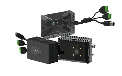
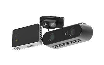
Modern industrial vision systems widely use ToF cameras (Time-of-Flight cameras) for:
- 3D measurement
- Robot obstacle avoidance
- Smart warehousing
- Industrial inspection
Depth maps can be converted into:
👉 Point cloud data
This enables 3D reconstruction, which is widely used in:
- Autonomous driving
- Industrial robotics
- AR/VR systems
6. Core Role of OpenCV in 3D Vision
OpenCV is widely used for:
- Camera calibration
- Coordinate transformation
- Image distortion correction
- 3D reconstruction
- Feature detection (SIFT, SURF, ORB)
Typical industrial workflow:
Image capture → OpenCV processing → coordinate transformation → 3D localization → machine control
7. Industrial Application Scenarios
Machine vision coordinate systems are widely used in:
- Industrial inspection
- Robot vision guidance
- Smart warehouse systems
- 3D measurement
- AI quality inspection
- SLAM navigation systems
These are all high-search-volume topics in Google SEO.
8. Conclusion
Machine vision coordinate systems and camera parameters are the foundation of modern industrial vision systems. From the OpenCV coordinate system, to world coordinate transformations, and further to 3D point cloud reconstruction with ToF depth vision, these technologies form the backbone of intelligent manufacturing.
With the advancement of Industry 4.0 and AI vision, understanding camera calibration, coordinate system transformation, and OpenCV-based 3D vision development has become an essential skill for engineers.
Synexens Industrial Outdoor 4m TOF Sensor Depth 3D Camera Rangefinder_CS40p

After-sales Support:
Our professional technical team specializing in 3D camera ranging is ready to assist you at any time. Whether you encounter any issues with your TOF camera after purchase or need clarification on TOF technology, feel free to contact us anytime. We are committed to providing high-quality technical after-sales service and user experience, ensuring your peace of mind in both shopping and using our products.